Primary: 6 turns of 3/8" copper with 3/8" spacing in a 30 degree inverted cone
Secondary: 6"dia (acrylic form) about 960 turns of #28 magnet wire Teminal Capacitor: 24x4" aluminum toroid (ok, ok it's dryer duct!)
Saftey: Saftey gaps on main transformer, caps on line feed, air/iron core filters, and RF line filters too!
Ground: Here's the best part...none! well, almost..the secondary is ground to the flight case ..sorta a counter poise
I am currently seeing over 32" sparks...andd tripping 20amp breakers! Whoohaaawww
Spark output would go up if I had a decent ground...
Future plans include a generator mounted on trailer for isolated power, and the van as counter-poise.
and all the mess below is a capacitor design that I have since scrubbed..but enjoy
..coco
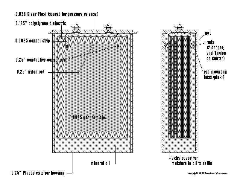
What I have here is a plate capacitor design for critique.
This unit is rated (calculated, not tested), at 15,000 volts it has a rated capacitance of 0.01 uf
The dielectric is 1/8th in. (0.125") poystyrene and are 10"x15"
The plates are 1/16th in. (0.0625") copper and are 9" x 14"
The left corner of every other plate is cut off at 45 degrees.
The right corner of every OTHER plate is also cut...this is to allow every other plate to be connected conductivly to each other with the 1/4" copper rods passing through the lest and right sides....the central rod is non conductive nylon and passes through all plates and dielectrics.
A nut on the ends of these rods holds the core together.
The rods pass through the nuts and into the mounting bosses, to hold the core suspended in mimeral oil.
The housing is 1/4" plastic (maybe acrylic..clearr for viewing), The top is scored by rec. to allow for pressure release in the evnt of failure.
Disregard the change in core pattern in the gif below..this happened on the computer and does not signify a design element.
Please take a moment to look it over, any questions, comments, or suggestions are very welcome....
Thanks!
Coco. coco@astroman.com
